All about AC Motors
Although a 3-phase induction motor is more efficient, some two-phase power motors are used. Also, the two-phase motor is used in many servo applications because transistor circuits can be used to control its speed and direction of rotation. Figure 1(A) shows the schematic diagram used to represent a two-phase ac motor. Each phase has a separate winding displaced 90° from the other phase winding. The rotor is squirrel-cage type just like that used in a 3-phase motor. Figure 1(B) shows the stator of two-pole, two-phase induction motor. Poles 1 and 3 are energized by phase A and poles 2 and 4 are energized by phase B. phase A and B of the supply voltage are 90° out of phase as shown in the voltage waveforms of Figure 1(C). This two-phase supply sets up a magnetic field in the poles of the stator. The magnetic fields combine to form a single resultant magnetic field. The strength and direction of the magnetic fields change in sequence to cause the resultant magnetic field to rotate. Just as in a 3-phase motor, the resultant magnetic field has a constant strength and rotates one complete revolution for one cycle of the ac supply voltage. This makes the synchronous speed 3600 rpm for a two-pole stator. The synchronous speed formula applies to the 2-phase motor the same as a 3-phase motor. Like a 3phase motor, a 2-phase motor can be made with more poles per phase to decrease the synchronous speed.
In Figure 1(C), phase a leads phase B by 90° causing the rotating field to turn clockwise. If either phase A or phase B is shifted 180°, the phase B will lead phase A by 90° and the rotating field will turn counterclockwise. Therefore, if we want to reverse the direction of rotation of any 2-phase motor, we can simply reverse the supply leads to one phase. The discussion on slip and torque given with the 3-phase motor applies equally well to a 2-phase motor.

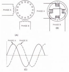
Figure 1
Wound Rotor Induction Motors
Some large induction motors use a wound rotor to increase the starting torque and give some speed control for the motor. Instead of using a squirrel-cage rotor, the rotor is wound with windings that are the same the stator windings. These windings are brought out to slip rings. Brushes ride on the slip rings providing connections to an outside circuit. This outside circuit is usually a variable resistance. During starting, maximum resistance is put in series with the windings as the motor comes up to speed, the resistance is decreased. At full speed, the windings are shorted.
Increased Starting Torque
You remember that when using a squirrel-cage rotor at slow speeds, the rotor field lags the stator field because of the inductance of the rotor. By putting resistance in the rotor circuit, we make the inductive reactance small compared to the resistance and the current in more nearly in phase with the induced voltage. Thus, the rotor field lags the stator field by s small angle and the motor produces more torque. This resistance also cuts down the amount of armature current for a given value of slip. As a result, the slip increases, increasing the armature current and the torque even with all the resistance shorted out, the wound rotor will have more slip than with the squirrel-cage rotor. The resistance of the windings will still be much greater than the resistance of the shorted bars in the squirrel-cage rotor. Therefore, while the wound rotor motor has better starting characteristics, the higher resistance of the wound rotor causes greater losses and poorer running characteristics than the squirrel-cage rotor.
Speed Adjustment
The speed of the wound rotor induction motor can be adjusted over a small range by adjusting the value of resistance in series with the rotor windings. The added resistance limits the rotor current causing the rotor slip to increase and the motor to run at a slower speed. Wound rotors are more expensive to build than squirrel-cage rotors. Therefore, wound rotor induction motors are used only where a large starting torque is needed or where some speed adjustment is required, making the increased cost of the wound rotor worthwhile.
3-phase synchronous motors
An asynchronous motor is an AC motor in which the rotor turns at the synchronous speed of the rotating field. The speed of the motor is locked to the frequency of the ac supply. Synchronous motors are used where constant motor speed is important. These motors are made in sizes ranging from 5000 hp or more down to one-millionth of a horsepower. The large power synchronous motors use 3-phase stator windings like 3phase induction motors. The stator of the 3-phase synchronous motor is exactly like the stator of the 3-phase induction motor we studied earlier in this lesson. Like the induction motor, this 3phae winding sets up a rotating magnetic field. The difference between the 3-phase induction motor and a 3-phase synchronous motor is in the rotor. Instead of the squirrel-cage rotor, the synchronous motor uses a dc electromagnet for the rotor. This electromagnet lock to the rotating magnetic field and the rotor turns at the synchronous speed with no slip.
DC-excited rotor
Direct-Current Field Excitation
In the early models, the field circuits excited from an external direct-current source. A dc generator may be coupled to the motor shaft to supply the dc excitation current.
Figure 2 shows the connections for the asynchronous motor. A field rheostat in the separately excited field circuit varies the current in the field circuit. Changes in the field current affect the strength of the magnetic field developed by the revolving rotor. Variations in the rotor field strength don’t affect the motor which continues to operate at a constant speed. However, changes in the dc field excitation do change the power factor of a synchronous motor.

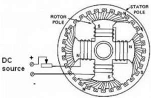
Figure 2
Brushless Solid-State Excitation
An improvement in synchronous motor excitation is the development of the brushless dc exciter. The commutator of a conventional direct-connected exciter is replaced with a three-phase, bridge-type, and solid-state rectifier. The dc output is then fed directly to the motor field winding. Simplified circuitry is illustrated in Figure 3. A stationary field ring for the ac exciter receives dc from a small rectifier in the motor control cabinet. This rectifier is powered from the ac source. The exciter dc field is also adjustable. Rectifier solid-state diodes change the exciter ac output to dc. This dc is the source of excitation for the rotor field poles. Silicon-controlled rectifiers, activated by the solid-state field control circuit, replace electromechanical relays and the contactors of the conventional brush-type synchronous motor.

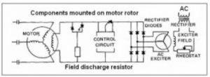
Figure 3
The field discharge resistor is inserted during motor starting. At motor synchronizing pull-in speed, the field discharge circuit is automatically opened and dc excitation is applied to the rotor field pole windings. Excitation is automatically removed if the motor pulls out of step (synchronization) due to an overload or a voltage failure. The brushless rotor is illustrated in Figure 4. Mounted on the rotor shaft is the armature of the ac exciter, the ac output of which is rectified to dc by the silicon diodes. Brush and commutator problems are eliminated with this system. (The stator of a brushless motor is similar to that of a brush-type motor.)

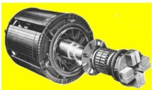
Figure 4
Starting Methods
This motor is not self-starting. It must be brought up to nearly synchronous speed before it will lock in step with the rotating field. This can be done by rotating the motor with a separate induction motor to bring the synchronous motor nearly up to speed. Then the excitation is applied to the rotor and the rotor locks to the rotating field. This method is seldom used because of the expense of the extra motor. Another starting method is to start the motor as an induction motor. Squirrel-cage type windings are wound on the rotor in addition to the regular rotor windings. The motor comes up to nearly synchronous speed as an induction motor. Then the dc excitation voltage is applied to the regular rotor windings and the rotor locks to the rotating field, turning the rotor at the synchronous speed. These motors may not produce enough starting torque t get the motor near synchronous speed when starting under load. In this case, you may find a clutch between the motor and the load. The motor is started with the clutch disengaged. When the motor is up to synchronous speed, the clutch is slowly engaged, bringing the load up to synchronous speed. Special rotor windings can be used to give the motor a high starting torque and bring the rotor up to synchronous speed. These rotors are expensive and are used only where the motor must be coupled directly to a heavy load. The rotor has high resistance squirrel-cage type windings to give the higher starting torque. The regular electromagnet windings are made of heavier wire and are excited by a lower dc voltage.
Constant speed
Synchronous speed = (120 × frequency) / number of poles OR S = (120×f) / p
Figure 5 shows the speed-torque curve for a typical synchronous motor. The dotted line shows the motor coming up to speed as an induction motor. When the dc excitation is applied, the rotor suddenly pulls into step with the rotating field. The 5-speed-torque curve becomes a straight line at 100 percent synchronous speed. The motor maintains this constant speed from no load to over 150 percent of full-load torque.


The amount of dc excitation used controls the power factor of the motor. If the excitation is weak, some of the magnetizing voltage for the rotor is taken from the ac supply. This causes a lagging power factor like an ordinary induction motor. If the excitation is increased above that needed for magnetizing the rotor core, the rotor is said to be overexcited. This causes a leading power factor. This feature is taken advantage of only in very large installations where it is desirable to correct the power factor as close to unity as possible.


1 Comment
An outstanding share! I have just forwarded this onto a friend who was doing a little homework on this. And he in fact bought me breakfast because I found it for him… lol. So let me reword this…. Thank YOU for the meal!! But yeah, thanx for spending some time to talk about this subject here on your web page.
Comments are closed.