What are the Basic types of transistors?
Today we are going to start learning about transistors. The term transistor comes from the current transferring resistor. The basic types of transistors are bipolar transistors. Previously we’ve talked about how diodes work. Diodes have a PN Junction.
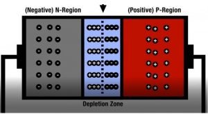
Figure 1
Bipolar junction transistors or BJTs are bipolar because they have 2 PN junctions. BJTs are essentially two diodes in a single package. The two main types are NPN and PNP transistors. NPN transistors have 2 N-type regions on either side of one P-type region while PNP transistors have 2 P-type regions on either side of one N-type region.
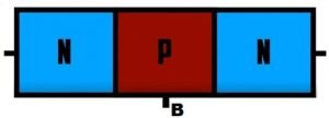
Figure 2
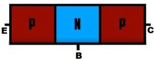
Figure 3
Bipolar transistors have three leads one going to each region typically the middle layer is the base P-type in the NPN and N-type in the PNP.
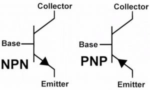
Figure 4
One of the other layers forms the emitter and the third the collector. These are labeled B, E, and C. This is the
the symbol for a diode the arrow points towards the N-type side.
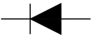
Figure 5
When we combine the P sections of two diodes, there are two arrows pointing out compare this to an NPN transistor symbol notice there is one arrow pointing out towards one of the N-type layers.
We know that the middle layer is always the base but the emitter and collector can appear on either side of the symbol. On the circuit symbol, the arrow is always on the emitter so we can tell which lead is the emitter and which is the collector by seeing which one has the arrow.
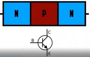
Figure 6
NPN transistor is similar except it has two N-type layers on either side of one P-type layer. On the PNP transistor symbol, the arrow on the emitter still points towards the N-type layer which in this case is in the middle. So the NPN transistor symbol has an arrow on the emitter pointing out while the PNP transistor symbol has an arrow on the emitter pointing in.
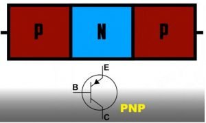
Figure 7
So how do transistors work? Rather than using a physical-mechanical switch, a transistor can act as an electronic switch using signals to turn it on and off. The main current in your circuit would flow through the collector and emitter while the signal current flows from the base to the collector.
The signal current at the base is what controls our switch. A current flowing from the base to the emitter can open the flow of current from the collector to the emitter. From our diodes lesson, we know that diodes require a forward voltage of 0.7 volts before they turn on allowing current to flow. In a standard NPN transistor when 0.7 volts is applied between the base and the emitter, the transistor turns on allowing current to flow from the collector to the emitter.

Figure 8 displays a biased NPN transistor circuit
Let’s look at an example. We’ll start with an NPN transistor. With an NPN transistor, we normally bias the device so that the collector voltage is positive with respect to the emitter. The voltage across these two points is referred to as the collector-emitter voltage or VCE. We would then connect the base to be positive with respect to the emitter this voltage is referred to as the base-emitter voltage or VBE.
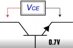
Figure 9
Here’s a circuit where a 9-volt battery connects with an LED and its resistor but it connects through a transistor. This means that no current will flow in that part of the circuit until the transistor turns on. To turn the transistor on, you need a VBE base-emitter voltage of at least 0.7 volts.
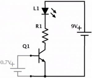
Figure 10
Imagine you have a small 0.7-volt battery when you apply the 0.7-volt battery from base to emitter, the transistor turns on. This allows current to flow from the collector to the emitter and thereby turning on the LED. So once the VBE reaches 0.7 volts the 9 volts from the main power source is available but don’t forget your voltage drop 0.7 volts is lost to heat in the transistor leaving 8.3 volts as your VCE.
Now let’s look at PNP transistors. For a PNP transistor rather than needing a minimum of 0.7 volts on the base of the transistor, there needs to be a minimum difference of 0.7 volts between the VCE collector-emitter voltage and the VBE base-emitter voltage. Let’s say our circuit power supply is a 9-volt battery again the base-emitter voltage would need to be no more than 8.3 volts for the transistor to turn on and allow current to flow between the collector and emitter.

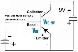
Figure 11
So if the base-emitter voltage is 8.6 volts, that’s only a difference of 0.4 volts. The transistor would be off and no current would flow. If the base-emitter voltage is 7 volts that is a difference of 2 volts which is more than 0.7 volts so the transistor would be on and current would flow between the emitter and collector. A difference of fewer than 0.7 volts off. A difference of more than 0.7 volts on.
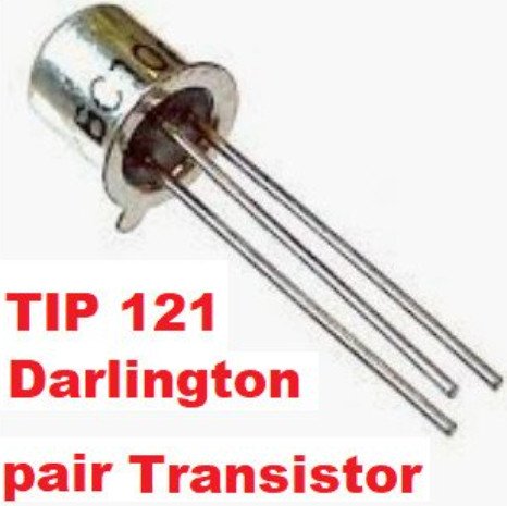
Another use for transistors is amplification. One method for current amplification is by combining two transistors into a Darlington pair. This can be done with two NPN or two PNP transistors. The two transistors are combined by connecting the emitter of the first transistor to the base of the second transistor.
In a Darlington pair, the current is amplified by the first transistor and then further amplified by the second. When a Darlington pair is contained in a single package, it makes a Darlington transistor. Like other transistors, it has three leads one base, one collector and one emitter.
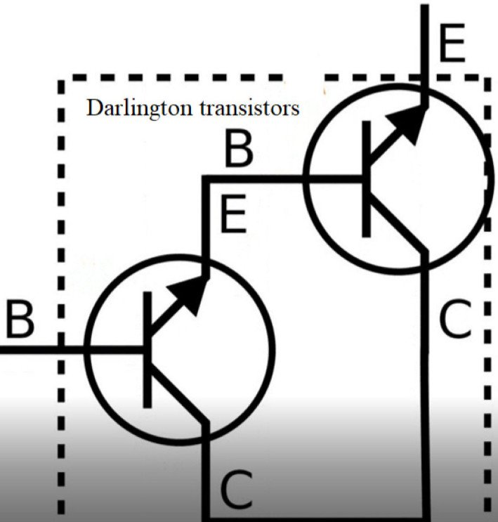
Figure 12
Darlington transistors are useful because only a small amount of current at the base is required in order to get a current gain of up to a thousand times or more. However, there is also a significant voltage to be considered.
There is a good amount of math involved when calculating currents and voltages when using Darlington transistors and really transistors in general. Here are some of the abbreviations used in those equations you should recognize some that I have already mentioned. Many of these can be seen on a transistor datasheet.
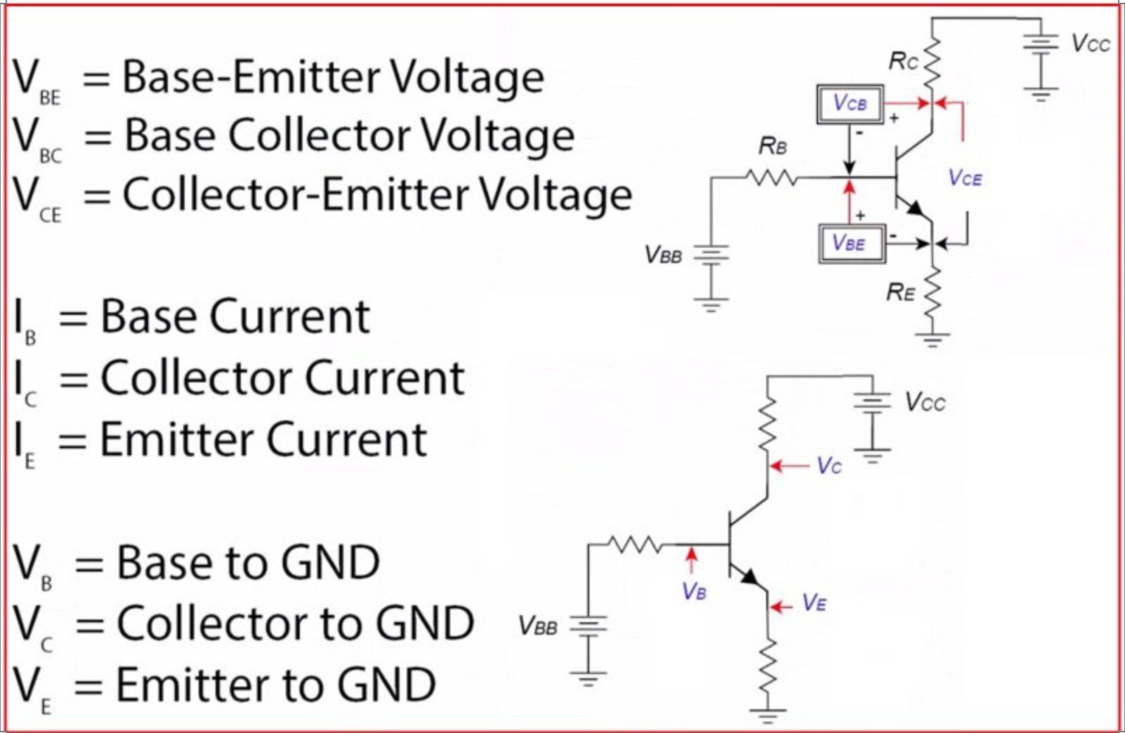
Figure 13
The last two types of transistors I’ll mention are Field-effect transistors. The two most common types are JFETs and MOSFETs but we’ll have to save those for another time. Transistors can be a little complicated to understand so I hope I gave you some good first steps to get you on your way.