
WeMos Lithium Battery Charging board, boost shield, TP4056 board to charge a Li-Ion LiPo PKCell Lithium Ion Polymer Battery – 3.7v 1200mAh LP503562
Let’s say you just created an awesome circuit that requires 5 volts to work properly and you want to make it portable. The easiest way would be to use a small Lithium Polymer battery in combination with a boost converter to step up the 3.8 volts of the battery to a stable 5-volt output but to prevent the battery from over-discharge, it is advisable to add a TP4056 board between the battery and the boost converter which also prevents the battery from short circuits and can even charge it up through the micro USB inputs. The only problems are that this setup is relatively big and thus not ideally suited for portable applications. So it would be best if we have one circuit which can charge up the battery, protect it from over-discharge, and short circuits and boost the voltage up to 5 volts.
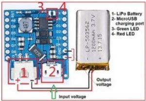
A popular board type that can handle most of these jobs is the Adafruit Power Boosts but needless to say they are not the most budget-friendly option. Luckily though, I recently found out WeMos D1 mini battery shields which can apparently charge up a Lipo battery and boost its output up to 5 volts. I did a couple of tests to determine all the available features of the board and measure the efficiency of the boost converter.
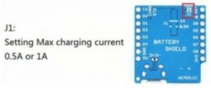
By measuring the voltage at the 5-volt pin, we can see that the circuit successfully boosts the voltage up to 5 volts without any problems. I started the testing by using a 5-volt power supply in order to charge up the battery to its charging cut-off voltage of 4.2 volts. After plugging in the micro USB cable, the red LED lights up and the battery gets charged up with a constant current of around 500 milliamps. And by shorting the two solder pads on the back (J1 see the next Figure), we should be able to increase the charging current to 1 Amp which was more like 700 milliamps at best but nevertheless, once 36 minutes has passed and the battery voltage reached 4 volts, the charging process entered the constant voltage modes.

And after a total time of around one and a half hours, entered a cut-off voltage of 4.186 volts the green LED lighted up which means the charging process was done. So all in all the constant current and voltage charging mode work nicely only the charging current was a bit low.
Another useful feature is that when the micro USB cable is connected, the boost circuit automatically disconnects and the 5-volt output delivers the USB power.
Now for the next tests, I connected my Lab Bench power supply to the battery input of the circuit since I can simulate different battery voltages with it and also set a current limit in case something goes wrong.
To start the efficiency tests, I first utilized a battery voltage of 4.2 volts, slowly increased the load on the output, wrote down the output current/power and the input power, and repeated this process until I had 4 values then I changed the battery voltage to 3.7 volts, repeated the measuring process and finally lowered the battery voltage to a rather low value of only 3 volts and obviously repeated the measuring process as well.
At this point, the highest output current draw was only around 40 milliamps so to increase up to the maximum claimed output current of 1 Amp, I replaced the load resistor with a couple of different high power resistors now while measuring the output and input power with those resistors the output voltage was pretty much constant at least until I used a 15 ohm resistor. This one drew 330 milliamps at 5 volts which seemed normal at first but once I lowered the input voltage down to the nominal voltage of the battery, the output voltage collapsed which means that the maximum output current of the circuit is only around 300 milliamps and not 1 amp. The first thing to notice is that the higher the battery voltage is, the higher the overall efficiency is. Next, it is also mentionable that the maximum efficiency of 90.2% is reached at a current draw of 110 milliamps and the overall efficiency never falls below 83% which is actually pretty decent so all in all the boost converter’s efficiency is fine but the maximum output current of only 300 milliamps is an eyesore. Now let’s see at which point the output voltage cannot maintain the 5-volt outputs by slowly decreasing the input voltage. As I can see at a voltage of around 2.6 volts, the output voltage breaks down close to underneath the input voltage. That basically means that there’s no over-discharge protection and this circuit will completely drain your battery if you are not careful. Last but not least, let’ set a current limit of 2 amps at the input and short the output of the circuits. As I can see, the output voltage breaks down but the short circuit current of 2 amps still flows which means that the circuit doesn’t feature short circuit protection either. So let’s come to a conclusion the charging of the lipo battery works decently, the boost converter works flawlessly as well but its maximum output current is pretty low.
But on the other hand, due to its low quiescent (idle state), the input current of only 13 micro-amps my 1100 milliamp-hour battery could power the circuit for 9.6 years. The only truly negative aspect of the circuit is that there is no over-discharge and short circuit protection but if you are familiar with electronics then this should be a fair trade for such a cheap $2 board.