
Let’s say you just got a new awesome electronic module that requires 5 volts in order to work but all you have is a 12-volt power source. The easiest solution would be to use an LM7805 voltage regulator with an input and output capacitor to step down 12 volts to 5 volts but if we measure the input and output power, we can see that the efficiency is quite low and gets even worse with higher input voltages because the regulator is basically a variable resistor that converts the excess power into heat which is not recommended when the power source is a battery.
To reach a higher efficiency though we can use a so-called Buck Converter. This one is very small, has an adjustable output voltage, doesn’t cost much, and also reaches a decent efficiency but how do these converters work, and can we even build one by ourselves? Let’s find it out!
A Buck Converter is a kind of SMPS or Switched Mode Power Supply. As an example, I will use an Arduino Nano which can switch its output pins on and off rapidly with its PWM function here I use the value 127 which creates a square wave with a duty cycle of 50%. If I now measure the voltage with my multimeter it already tells me that we successfully stepped down our 5 volts to 2.5 volts because it measures the average and for undemanding components like LEDs this method already does a trick but in order to control higher voltages and bigger current draws, we need to upgrade the switch to a P-Channel MOSFET by opening up 12 volts to source a 10 kilo-ohm Pull Up resistor between gate and source, the gate also to the PWM signal and drain to loads such as a small light bulb and by connecting a potentiometer to an analog input and adjusting the code a bit, I can also control a duty cycle and thus increase or decrease the average voltage and brightness of the bulb but our switched voltage still has high voltage peaks which will destroy sensible 5-volt electronics so we have to get rid of them.
To do that I firstly added 100 microhenry inductor in series to the loads this way the current cannot rise instantly because a part of the energy is stored in the electromagnetic field of the coil and once the switch opens, the electromagnetic field collapses and should pump a current through the load which it doesn’t do properly instead we get those massive voltage spikes at the switch which is not a surprise since there is no complete loop in which the current could flow and thus an electron excess occurs. That is why I added a Schottky diode with low forward voltage to the circuit so that current can flow when the switch is open but the resulting current flow is still far away from a steady value to further improve that, we need to increase the frequency of the PWM signal which is right now around 976 Hertz. I simply change the pre-scaler in my sketch, uploaded it and promptly got a frequency of 62.5 kilohertz. With such a short uptime, the energy storage capacity of the inductor is now enough to smoother the current flow quite a bit that is also the reason why switched-mode power supplies usually use a high frequency in order to keep energy storage components small. All that was left to do with my design was adding a 47 microfarad capacitor on the output to smooth out the voltage and the Buck Converter was complete and reached an efficiency of 67% with my light bulb at 5 volts which are not terrible but once I change this big load to something smaller, like a 50-ohm resistor, the output voltage jumped up to 8.5 volts that mean we need to use a voltage divider which provides a feedback voltage to a control system in order to adjust the duty cycle and thus keep the output voltage steady no matter what load is attached and since this is getting a bit complicated, let’s keep things simple with this LM2576 simple switch IC (Figure 1 illustrates an internal block diagram of LM2576).

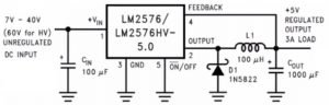
Figure 1 illustrates an internal block diagram of the LM2576 IC
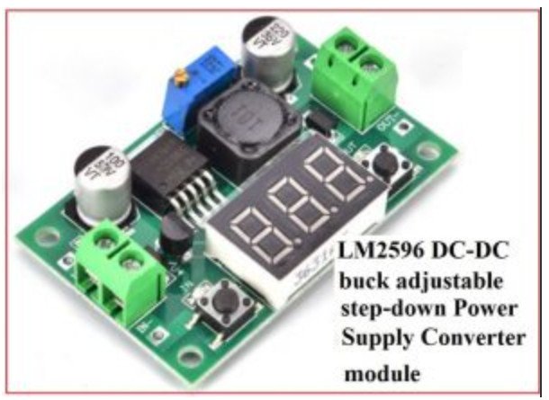
I have the 5-volt version that has a feedback resistor integrated and also only requires 4 additional parts to build up a complete Buck Converter (Figure 2 illustrates LM2576 and 4 other elements to build a simple but effective Buck converter Power supply).
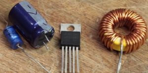

Figure 2
The rule of thumb will be recreating this schematic is to keep all the parts close together in creating thick sort of traces after only 10 minutes of soldering, the circuit was complete, works flawlessly and obviously reached a better efficiency than my demonstration circuit and if you want to make your own Buck Converter I can recommend the adjustable version of this IC there you can add your own feedback resistors or potentiometer to create an adjustable output voltage and with that being said, you already know quite a bit about stepping down voltages efficiently with a Buck Converter.