SIEMENS TC35 SMS Module Board RS232 UART Serial Arduino + Voice adapter
INTRODUCTION AND OVERVIEW
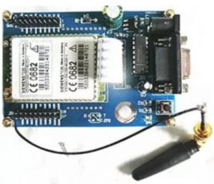
GSM is known as Global System of Mobile Communication. It is being used as a standard for nowadays in our cell phone. Over 200 countries and 2 billion people are using it as a phone today. GSM would work any place as long as the signal/network is available. Most likely it is operating in the 900MHz to1800MHz band. This GSM Development Board uses Siemens TC35 GSM module as the central working unit. It comes with the following features:
Siemens TC35 GSM module on board
Support 900/1800/1900 MHz GSM Tri band.
Uses AT Command Set.
SIM card holder/socket ready
Ready with SMA antenna for better signal reception and transmission
SMS (text) and voice communication is ready.
Single board solution.
Power with 7-15VDC.
Ready with UART (2.65V TTL) and RS232 (COM Port) serial interface.
Serial Interface, Baud rate: 9600bps, 8-1-N
Onboard 3.5mm earphone jack and mic jack
Onboard buzzer as a sound indicator.
5 LED act as an indicator with different modes.

In this document, I will show you how to handle a TC 35 GSM module properly and also how to send SMS with it by the use of an Arduino Uno.
On the backside, we also see that we need a SIM card. I recommend a simple prepaid card you could put it in the board like this but it makes things a bit easier later on if we first put it in a smartphone to remove the SIM lock. Afterward, we can insert the card into the holder on the board and lock it in place.
Now we need to power the board we can use the DC jack or the VCC and ground pins on the board. Please do not try other pins! I recommend 5 volts because the MAX232 IC here which is necessary to communicate with the module through a RS 232 port is directly connected to VCC and ground.
We have to press the button on the right side of the RS232 port to start the login process to the mobile network. When the status LED blinks shortly every 2 to 3 seconds then you know that the module is connected successfully but this button itself is not practical if you want to automate something with a microcontroller so I used my multimeter to find out that the left side of the switch is ground and the right side is connected to the module as an input. Whenever the right side connects to ground, the login process begins. I solved this by soldering a jumper wire to the right side of the switch which connects to pin DO10 of the Arduino Uno (check the schematic on Figure 1

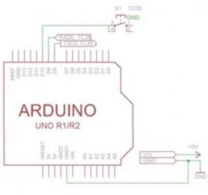
Figure 1
Whenever this pin goes low, the login process starts. The board then draws around 13 milliamps while being in this state. I connect TX to TXD0 and RX to RXD0. Even though TC 35 uses 3.3-volt logic levels, it is compatible with the 5-volt signals of the FTDI (Future Devices International Technology) and Arduino. Do not worry about that I start the Arduino software, select the port of the FTDI chip and open the serial monitor. Baud rate is 9600 and carriage return is selected.
The module uses simple AT commands to communicate. All of those are listed in the AT command reference. For example, if I type in AT, I get an OK. That means it works or I can get some other basic information like my network operator or the signal strength. Now let’s move this to the Arduino. The wiring is super easy again check out the schematic.
This sketch here showcased the method of sending SMS pretty good. I just open the serial monitor which pulls the startup switch low then I can enter my SMS and finish it with a dot at the end. Don’t forget that dot! Now the program does all the work by itself and you receive the SMS on the smartphone with the number you entered in the code.
Now you can, of course, adapt the code to fit your needs you basically just need the function SendTextMessage all the other stuff are just gimmicks.