DELTA , Allen Bradley MICROLOGIX 1500 PLC programming skill Test 2
What is purpose of this project?
In this project I wish to write a PLC control program to control the 16-Floor Simulator system using a DELTA PLC and a VEIVIEW HMI device that is already designed a while ago. To know more about the 16-Floor Simulator system, click HERE.
To view the performance of the 16-Floor Simulator system in action, click HERE.
In this project, I would like to develop a PLC control program that when it is executed, it will control the Simulator to take some steps. The developed program can be specially used to find out how much “time” it can take for a novice PLC programmer to develop a control program similar to the one presented here. Of course the less time it takes for one to develop a similar code, the better. If one can develop such a control program for a PLC in about an hour or less, that is good. It means such a person, has the ability, knowledge and talent to be a good programmer in the future.
I use these types of small practical test programs when I tend to test the programming skills of applicants when they apply for a PLC programming job opening.
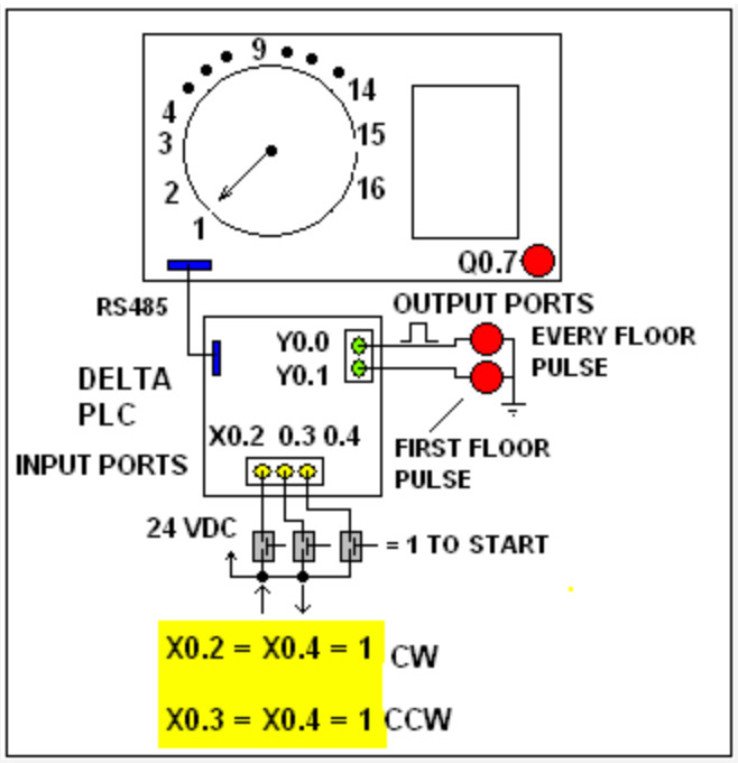
As depicted in Figure 1, I/O terminals of the DELTA PLC control hand indicator, cabin door, the hand rotational speed and direction and image LED of the whole Simulator. The simulator control system is generated such that when X0.2 = X0.4 = 1 (switched on with 24 V DC), the indicator revolves CW (clockwise) which simulates the Cabin traveling upward.
When X0.3 = X0.4 = 1, the indicator revolves CCW (counterclockwise) which simulates the Cabin traveling downward. Anytime the indicator is pointing at floor # “1”, Y0.1 = 1 and stays “ 1” as long as the indicator does not change its position. Anytime the indicator travels from any floor # to the next or to a previous one, Y0.0 is going to shift from 0 to 1 and back to 0 in 0.5 seconds. Anytime the X0.7 = 1, small Lamp image on the HMI device turns on. The Lamp image turns off when X0.7= 0.

Figure 1 shows the schematic of the 16-Floor Elevator control simulator system.
What is the purpose of generating a second control program in this project?
Developing a control program such as this can be specially used to find out how much “time” it can take for a novice PLC programmer to develop a control program similar to the one presented here. Of course the less time it takes for one to develop a similar code, the better. If one can develop such a control program for a PLC in about an hour or less, that is good. It means such a person, has the ability, knowledge, and talent to become a good PLC programmer in the future.
I use these types of small practical test programs when I tend to test the programming skills of applicants when they apply for a PLC programming job opening.
A little information about the DELTA PLC input/output terminals
As depicted in Figure 1, I/O terminals of the DELTA PLC control the whole Simulator. The system PLC is programmed such that when X0.2 = X0.4 = 1 (switched on with 24 V DC), the indicator revolves CW (clockwise) which simulates the Cabin traveling upward. When X0.3 = X0.4 = 1, the indicator revolves CCW (counterclockwise) which simulates the Cabin traveling downward. Anytime the indicator is pointing at floor # “1”, Y0.1 = 1 and stays “ 1” as long as the indicator does not change its position. Anytime the indicator travels from any floor # to the next or to a previous one, Y0.0 is going to shift from 0 to 1 and back to 0 in 0.5 seconds. Anytime the X0.7 = 1, the small Lamp image on the HMI device turns on. The Lamp image turns off when X0.7= 0.
How the Control program should work?
You are given the hardware as depicted in Figure 2 in which a second MicroLogix 1500 PLC is hardwired to the Simulator as shown. You are asked to develop a code to control the 16-Floor elevator simulator system PLC as
following:
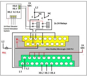
Figure 2 shows the hardware connection of both I/O terminals of the PLCs
STEP 1: When PB1 = 1 (I0.2) depressed momentarily (depressed and release for 1 second manually), the indicator to revolve (from any current floor number it is indicating) in CCW direction to point to the 1st floor. While indicator points to Floor # 1, Q0.7 turns “on and off” for 2 seconds (with a period of 1 second). At the end of the flashing time, Q0.7 (image LED indicator is located on the bottom right side of the LCD HMI device) is turned off and control of the main program starts the execution of STEP 2.
STEP 2: The indicator starts rotating in CW direction to pass floor number “2” and at 3rd-floor #, it again stops and Q0.7 starts flashing. At the end of the flashing time, Q0.7 is turned off and the control of the main program continues from STEP 3.
STEP 3: The indicator starts rotating in CW direction to pass floor number “4” and the 5th-floor #, it again stops and Q0.7 starts flashing. At the end of the flashing time, Q0.7 turns off, and the execution of STEP 4 starts.
STEP 4: The indicator starts rotating CW to pass floor number “6” and at the 7th-floor #, it again stops and starts flashing Q0.7. At the end of the flashing time, Q0.7 turns off, and the execution of STEP 5 starts.
STEP 5: The indicator starts rotating in CCW direction and repeats stops at floor # 6, # 4, and finally it comes to a complete stop at floor number 2. At the end of step # 7, the system is placed in “stand by” status and re-executes all the mentioned steps when PB1 (I0.2) is depressed again.
Figure 3 displays the designation of all I/O and power terminals on the panel of the Allen Bradley MicroLogix 1500 PLC.
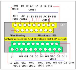
Figure 3
To download the developed program for this project, click HERE !