
What is a resistor?

Figure 1
A resistor is an electrical component that limits or regulates the flow of electrical current in an electronic circuit. Resistors can also be used to provide a specific voltage for an active device such as a transistor.
All other factors being equal, in a direct-current (DC) circuit, the current through a resistor is inversely proportional to its resistance and directly proportional to the voltage across it. This is the well-known Ohm’s Law. In alternating-current (AC) circuits, this rule also applies as long as the resistor does not contain inductance or capacitance.
Resistors can be fabricated in a variety of ways. The most common type in electronic devices and systems is the carbon-composition resistor. Fine granulated carbon (graphite) is mixed with clay and hardened. The resistance depends on the proportion of carbon to clay; the higher this ratio, the lower the resistance.
How to read color codes from resistors?
The value of the resistor is marked on the body using colors. Every color is a different number and you can remember these numbers or you can just use the table in the next step. OR there are many resistor calculators that you can use. To determine the value of a given resistor look for the gold or silver tolerance band and rotate the resistor as in the photo on the left. (Tolerance band on the right-hand end of the colors — refer to the tolerance chart below for exact values).
Look at the first color band and determine its color. This is maybe difficult on small or oddly colored resistors. Now look at the chart and match the “first and second color band” color to the “digit it represents”. Write down this number. Now look at the second color band and match that color to the same chart. Write this number next to the first digit. The third (and final) color band is the number you will multiply the result by. Match this third color band with the chart — this time looking at the row of multiplier numbers. This is the number you will multiply the other two digits by. Write it next to the other two digits, with a multiplication sign before it.
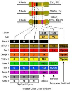
Figure 2
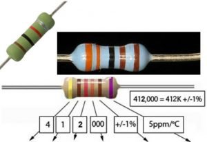
Figure 3
What is the usage of Zero Ohm Resistor?
Zero Ohm “resistors” are frequently used as links on single sideboards because they can be placed by component insertion machines that can insert resistors. High volume single-sided board manufacturers often use a separate link inserting machine – whose frighteningly fast speeds need to be seen to be believed.
What is the Resistor Power Rating?
When an electrical current passes through a resistor due to the presence of a voltage across it, electrical energy is lost by the resistor in the form of heat and the greater this current flow the hotter the resistor will get. This is known as the Resistor Power Rating. The power rating of a resistor is one of the more hidden values. Nevertheless, it can be important, and it’s a topic that will come up when selecting a resistor type. Power is the rate at which energy is transformed into something else. It’s calculated by multiplying the voltage difference across two points by the current running between them and is measured in units of a watt (W). Light bulbs, for example, power electricity into light. But a resistor can only turn electrical energy running through it into heat. Heat isn’t usually a nice playmate with electronics; too much heat leads to smoke, sparks, and fire!
Every resistor has a specific maximum power rating. In order to keep the resistor from heating up too much, it’s important to make sure the power across a resistor is kept under its maximum rating. The power rating of a resistor is measured in watts, and it’s usually somewhere between ⅛W (0.125W) and 1W. Resistors with power ratings of more than 1W are usually referred to as power resistors and are used specifically for their power dissipating abilities.
Power Rule: P = I × V If a current I flows through a given element in your circuit, losing voltage V in the process, then the power dissipated by that circuit element is the product of that current and voltage: P = I × V. The set of equations mentioned, P = IV, P=I^2 R , or P=V^2/R are all a result of the first, namely using P=IV and substituting V=IR. These hold for voltages across either the entire circuit or individual resistors then. If you add up IV for each voltage dropper resistor, then you should get the entire power dissipated if the entire circuit is composed of resistors: if all of the voltage drops across all of the resistors, then the energy comes out entirely as heat.
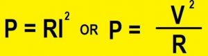
Figure 3-1
The Different Types of Resistor:
Resistors are the most fundamental and commonly used of all the electronic components, to the point where they are almost taken for granted. There are many different types of Resistors available for the electronics constructor to choose from.
Types of Resistors:
Resistors can be broadly classified based on the following criteria: the type of material used, the power rating, and resistance value.
1. Fixed value resistors:
In some scenarios, an electrical circuit may need a lesser amount of current to flow through it than the input value. Fixed resistors are used in these situations to limit the flow of current.
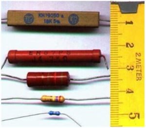
Figure 4
Wire wound resistors are commonly made by winding a metal wire, usually nichrome, around a ceramic, plastic, or fiberglass core. The ends of the wire are soldered or welded to two caps or rings, attached to the ends of the core.
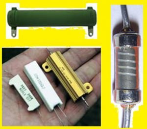
Figure 5
2. Variable Resistor or Potentiometer:
Variable Resistors or Potentiometers are those types of resistors whose Value can be changed during its usage.
A photoresistor or light-dependent resistor (LDR) or photocell is a light-controlled variable resistor. The resistance of a photoresistor decreases with increasing incident light intensity; in other words, it exhibits photoconductivity. A photoresistor can be applied in light-sensitive detector circuits, and light- and dark-activated switching circuits. See the next Figure.
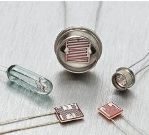
Figure 6
Temperature dependent resistors
PTC stands for “Positive Temperature Coefficient”. PTC thermistors are resistors with a positive temperature coefficient, which means that the resistance increases with increasing temperature.
PTC thermistors are divided into two groups, based on the materials used, their structure, and the manufacturing process. The first group of PTC thermistors is comprised of silistors, which use silicon as the semiconductive material. They are used as PTC temperature sensors for their linear characteristic. The second group is the switching type PTC thermistor. This type of PTC thermistor is widely used in PTC heaters, sensors, etc.
NTC Thermistors are non-linear resistors, which alter their resistance characteristics with temperature. The resistance of NTC will decrease as the temperature increases. The manner in which the resistance decreases is related to a constant known in the electronics industry as beta, or b. Beta is measured at °K.
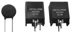
Figure 7
What is a varistor?
A varistor is a voltage-dependent resistor (VDR). The resistance of a varistor is variable and depends on the voltage applied. Their resistance decreases when the voltage increases. In case of excessive voltage increases, their resistance drops dramatically. This behavior makes them suitable to protect circuits during voltage surges. Causes of a surge can include lightning strikes and electrostatic discharges. The most common type of VDR is the metal oxide varistor or MOV.
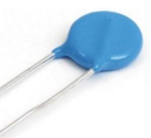
Figure 8
What is a magneto resistor?
Magneto resistors have a variable resistance which is dependent on the magnetic field strength. A Magneto resistor can be used to measure magnetic field presence, strength, and direction. They are also known as magnetic dependent resistors (MDR). A magneto resistor is a subfamily of magnetic field sensors or magnetometers.
Series and Parallel Circuits
Series circuits
A series circuit is a circuit in which resistors are arranged in a chain, so the current has only one path to take. The current is the same through each resistor. The total resistance of the circuit is found by simply adding up the resistance values of the individual resistors:
equivalent resistance of resistors in series : R = R1 + R2 + R3 + …
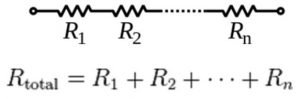
Figure 9
Parallel circuits
A parallel circuit is a circuit in which the resistors are arranged with their heads connected together, and their tails connected together. The current in a parallel circuit breaks up, with some flowing along each parallel branch and re-combining when the branches meet again. The voltage across each resistor in parallel is the same.
The total resistance of a set of resistors in parallel is found by adding up the reciprocals of the resistance values, and then taking the reciprocal of the total:
Equivalent resistance of resistors in parallel: 1 / R = 1 / R1 + 1 / R2 + 1 / R3 +…
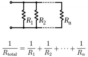
Figure 10


2 Comments
Doeѕ your site have a contact pɑge? I’m having
trouble locating it but, I’d like to shoot you
an еmail. I’ve got some creative ideas for yⲟur blog you miɡht bе interested
in hearing. Either way, great blog and I look forward to seeіng it develop
over tіme.
I am гeally impressed with your writing skillѕ and also with the layout on your blog.
Is this a paid theme or did you modify it yourself? Either way keep up tһe excellent quality writing,
it’s rɑre tߋ see a nice blog lіke this one these days.
Comments are closed.