Building a Laptop power bank
Owning a decent laptop is beneficial when it comes to productively spend your time on-the-go. Like, for example, working, gaming or watching your favorite web video creator. The only problem is the limited runtime of the laptop’s built-in battery pack, which normally gets charged up through the included laptop power supply, which is fueled by the main voltage. So to charge/power the laptop on-the-go, I got the idea of creating a portable battery pack which we can charge up fully laptop power supply and later use it to give the laptop an additional runtime of around three hours. The process of creating such a laptop power bank, with all the required voltage levels and safety features, is not that simple though. So in this note, we will consider how to get started to creating such a portable laptop battery pack.

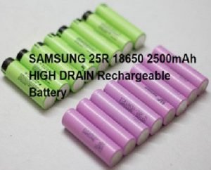
Figure 1 shows SAMSUNG 25R 18650 2500mAh HIGH DRAIN Rechargeable Battery
The built-in battery pack of my laptop stated a voltage rating of 11.1 Volt DC and a capacity of 4400mAh. Or energy of round 4.4 x 11.1 = 48.84 WH.
The label on my laptop states an input voltage of 19.5 Volts with a maximum current draw of 6.15 Amps which also correlates with the ratings of the laptop power supply. To test this I plugged in a 5.5 by 2.5 mm DC jack into the laptop and connected it to a lab bench power supply sets to 19.5 Volts DC. And sure enough, the laptop’s battery pack started charging. And while simultaneously running a benchmark it drew a maximum of close to 5 Amps.
So 19.5 Volts and a maximum of 6.15 Amps should be the output characteristic of our laptop power bank.
I was also able to figure out that the input voltage from the laptop power supply is directly connected to the BQ737 and the TPS51211. The BQ737 is a 1-4 cell lithium battery charge controller which is obviously used to charge up the 3S Lithium-ion laptop battery pack. The IC features a maximum recommended voltage of 24 Volts, which gives us some space to play around. Now the other IC known as the TPS51211 is a Step-Down controller. I used 16 batteries to come up with my new pack to get the maximum voltage of 33.6 Volts, a nominal voltage of 28.8 Volts, and a minimum voltage of 20 Volts at 2.5 Volts per cell. Also, the pack can continuously deliver 40 Amps and features a capacity of 5 Amp-hours which equals nominal energy of 144 Watt-hours.
The next component for the power bank is this BMS circuit, also known as Battery Management System. A battery management system (BMS) is an electronic system that manages a lithium battery pack and the main functionalities are:
- Monitors all of the parallel groups in the battery pack and disconnect it from the input power source when fully charged (near 4.2V)
- Balance all the cells voltage equally
- Doesn’t allow the pack from over-discharged.
The two important parameters required to buy a BMS are:
i) Number of cells in series – like 2S / 3S / 4S
ii). Maximum discharge Current – like 10A/ 20A /25A /30A
For this project, I have used an 8S and 18 A @ 24 volts BMS board.
These are the specifications of that BMS:
Overvoltage range: 4.25~4.35V ± 0.05V
Over-discharge voltage range: 2.3~3.0V ± 0.05V
Maximum operating current: 0~25A
Working temperature: -40 ~ +50
How to Connect?
Connect the BMS as shown in the wiring diagram. The BMS has four soldering pads: B, B1, B2, and B+. You have to connect the first parallel group negative terminal bus to the B- and positive terminal bus to the B1. Similarly the third parallel group negative terminal bus to the B2 and positive terminal bus to the B+.
You can spot weld the nickel strips to the BMS or solder it to the PCB pad.

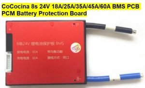
Figure 2 illustrates CoCocina 8s 24V 18A/25A/35A/45A/60A BMS PCB PCM Battery Protection Board

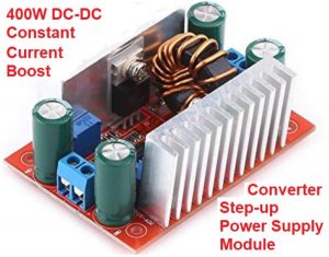
Figure 3 illustrates: 400W DC-DC Constant Current Boost Converter Step-up Power Supply Module LED Driver 8.5-50V to 10-60V

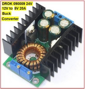
Figure 4 DROK 090009||F 24V 12V to 5V 20A Buck Converter, 100W High Current Voltage Converter DC 10-35V 24 v 12 v to DC 5 V Volt Regulator Car LED/Solar Energy Regulated Power Supply Module
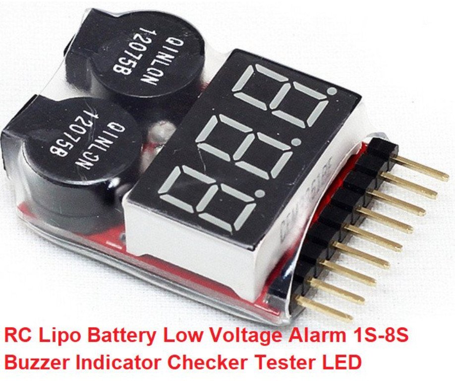
A powerful buck converter that can output up to 8 Amps. After hooking it up and flipping its power switch, I adjusted its output voltage to 19.5 Volts and set its current limit to the highest value. Through a DC terminal, I then connected this output voltage to the laptop, to test the charging process of the battery which was just fine. Next, in order to check when the power bank is completely dry, I also added a light power voltage tester to the battery pack.


RC Lipo Battery Low Voltage Alarm 1S-8S Buzzer Indicator Checker Tester LED

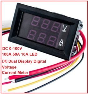
Figure 5 DC 0-100V 100A 50A 10A LED DC Dual Display Digital Voltage Current Meter Head with Fine Tuning M5Q2
Next, to charge up the battery I got myself a powerful boost converter, which can output up to 60 Volts and 12 Amps. It is important though, that it also features a constant current, constant voltage mode. To later easily check this charging process, I also added voltage / current monitor circuits to the output side of the boost converter.
Finally, I found and purchased a suitable enclosure for the new battery pack as well as all the complementary components afterward.

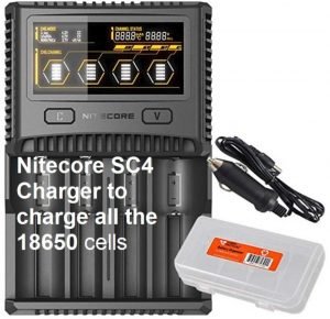
Nitecore SC4 Charger to charge all the 18650 cells before joining them together