Building a 3-phase signal generator circuit using the AVR ATmega16 microcontroller
Abstract:
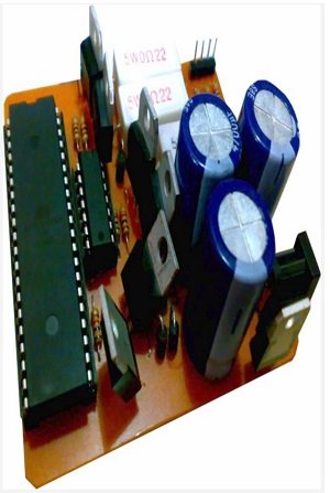
In this project we want to design a circuit based on a microcontroller to generate three signals on its outputs with the following features (Figure 1):
1- The used power supply is 12v DC (such as car batteries)
2- The frequency of the output signals is 50hz.
3- The three signals have a 120-degree difference in their phases.

Figure 1
In attendant files, you can find the written program source with CodevisionAVR software. The design and simulation of the circuit (Figure 1) by Proteus software and also its PCB design with Altium designer to build the circuit.
Program:
At first, we write a program on a microcontroller to generate three PWM signals by 120° Phase difference. We use an ATmega16 because it has three PWM outputs. The program is written in C language and it’s simple too.
To view the code, please download the relevant files by clicking HERE
In the Codewizard we active three timers with 1MHz frequency in the fast PWM mode. Notice that the Timer1 is 16bit and we want to have three outputs with the same curve. So we have to have the following setting for this timer Fast PWM top=0×00FF. Also, we active the timers overflow interrupt and program them on non-inverted mode Then we write the following instruction in these three interrupts.
We start with the timer2 interrupt to explain the above program. In this interrupt when timer2 overflows and its pulses width is increasing (c=0) then we increase the width of timer2 pulses until it reaches a maximum value. In this case, the flow is reversed and the pulse width gradually decreases. We will have three sinusoidal signals on timers’ output with writing the same program in two other interrupts.
What do we have to do to keep a 120° phase difference? The timer0 does this task. When the pulses width reaches its maximum value (or in other words, we are on a positive pick of a sinusoidal signal) then #84 is allocated to the OCR register of timer1, and its flow changes to ascending mode. And when we reach a minimum value of OCR, we change the OCR value of timer2 and put it into the ascending mode. In every cycle buy this work, it takes to keep a 120° phase difference between the signals. Hardware At first we wrote a program on a microcontroller to generate three PWM signals by a 120° deference phase in the previous section. Then these signals are given to the Base pin of some transistors. These switch transistors amplify PWM signals with a DC 12v power and then give them to an RC circuit to change the switching signals (PWM signal) to Sinusoidal signals. You can see the circuit diagram in Figure 2.
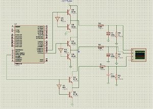
Figure 2
The above circuit tests with Proteus software and Figure 3 show its performance.
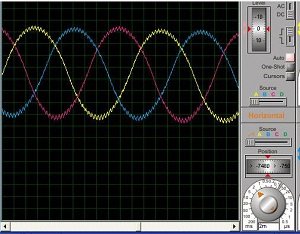
Figure 3
Figure 4 displays the Pin Configuration of the AVR ATmega16 microcontroller.
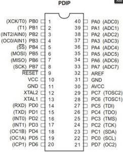
Figure 4


1 Comment
Hi there, all is going fine here and ofcourse every one is sharing information, that’s genuinely good, keep up writing.
Comments are closed.