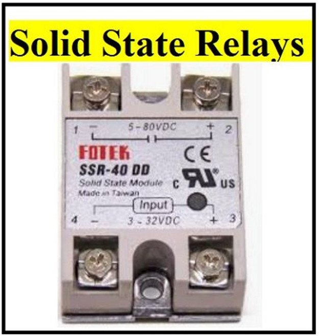
All about Solid State Relays and TRIAC ICs : BTA16 TRIAC and MOC3063 optocoupler
When it comes to switching on and off an AC appliance a relay can handle this job without a problem. A relay is a rather powerful electromechanical switch that can switch big loads, has very low contact resistance so basically no power loss on the AC side and offers galvanic isolation.
The only problem is that a relay is still partly mechanical which means it switches rather slow, doesn’t switch silent, its contacts wear out over time, spots can form when the contacts open and the coil needs to be constantly powered. To counteract those problems another kind of relay an entirely electrical relay became popular the so-called solid state relay and even though you can get such a powerful 40 amp solid state relay for around 3 to 4 dollars from China nowadays.

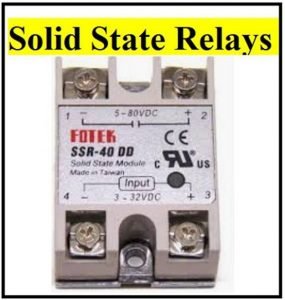
Figure 1 displays a typical solid state relay module made by FOTEK
Let’s talk about the basics of such solid state relays because even though they have the word “relay” in the name they actually have very little to do with the relay we are familiar with. For starters, they all have an input side and a load side. On the load side, we can simply connect our AC appliance in combination with our AC voltage just like how we would do it with the contacts of a traditional relay.

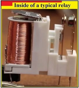
Figure 2: displays the inside of a typical relay
On the input, we simply must apply the DC voltage the solid state relay presents on its enclosure in order to let current flow through the input which thus closes the switch on the load side and therefore activates the AC appliance.
It is actually pretty easy so let’s build up a test circuit with an AC voltage of 24 volts for safety reasons and a 1-kilo ohm resistor on the load side and a 5-volt input voltage. After applying the input voltage we immediately notice that the input current/power of a solid state relay is way lower than the input current/power of a traditional relay.
And if we take a look at the voltage across the 1 kilo-ohm resistor on the oscilloscope, we can see the mains voltage sine wave which means the load switch works without a problem but if we measure the maximum voltage across the resistor, we only get a value of 35.4 volts while the output voltage of my transformer features a peak voltage of 36.2 volts.
That means there is a noticeable voltage drop of around 1.46 volts across the load contacts of the solid state relay which obviously represents a power loss. To get a better understanding of this problem though I removed the load and voltage source from the load side and instead directly connected my lab bench power supply which I set to a current limit of 1 amp.
This current flow created a voltage drop of 0.87 volts across the load contacts and therefore with an increasing current demand on the load side we produced more and more power losses which is a big disadvantage in comparison to traditional relays but at least it should be able to switch my light bulb example right here on and off a lot faster.
After applying a 1 kilohertz square wave to the input we can see that the output contacts stay closed even when I completely remove the input voltage. The reason is that the main component of the solid state relay is a so-called TRIAC.
The main point is that a TRIAC features a holding current which means that the TRIAC will stay conductive until the current flow falls underneath this value. So in a nutshell switching DC voltage with a solid state relay is pretty redundant so let’s rather go back to the AC circuit on the load side.
As you can see by utilizing a rather high frequency pretty much all half waves of the AC voltage gets let through but if we decrease the frequency underneath the 50 hertz mains voltage frequency, we can observe quite a few interesting aspects of the switch.
First off, the solid state relay can only turn off near a zero point since the current flow is only near this point underneath the holding current.
Next, the switch does only turn on near a zero point as well which granted reduces the initial surge current and thus the electromagnetic interference that a relay can for example easily produce but on the other hand this feature makes phase angle control impossible which could have been used to control the power of our AC appliance.
The reason is that this solid state relay is the zero crossing type which like the name implies only turns on near a zero point. What we would need for phase angle control is a non-zero crossing solid state relay which of course also does exist.
The last mentionable feature of the switch type is that just like the relay it offers a galvanic isolation between the input and load side which makes it safe to use with for example a microcontroller and now that we’ve got the basics out of the way and learned that a solid state relay does eliminate a few dozens of problems of the traditional relay while also adding a few new disadvantages how can we actually build one ourselves?
A commercial solid state relay is consisted of a BTA16 TRIAC which can actually only handle 16 amps instead of the claimed 40 amps. The MOC3063 optocoupler with an integrated zero crossing circuit and an SS8050 NPN transistor.

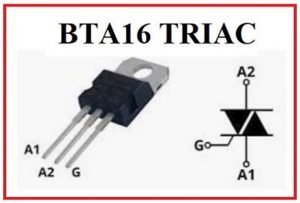
Figure 3: displays BTA16 TRIAC IC

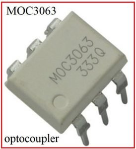
Figure 4: displays MOC3063 IC

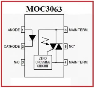
Figure 5: displays the internal block circuitry of the MOC3063 optocoupler
And by following the traces of the PCB and doing a bit of continuity testing I came up with a schematic for the commercial product which should be more or less correct. What we got as a simple TRIAC switch circuit that is activated by an optocoupler.
That is why I dug through the components I had laying around and came up with my own even simpler circuit. What I utilized as the TRIAC is a BT138 which can only handle 12 amps but on the other hand is dirt cheap. For the optocoupler I went for the MOC3020 which you can also get inexpensively and in comparison to the commercial product does not include a zero crossing circuit which means my version of the solid state relay can be used for phase angle control.

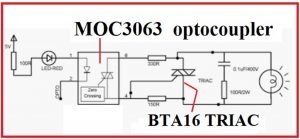
Figure 6: displays wiring diagram of MOC3063 and BTA16 ICs
The rest of the components are pretty much just current limiting resistors whose values can easily be calculated and with the theory being completed I gathered all the required components and soldered them all to a small piece of perfboard.

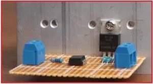
Figure 7: displays the prototype of the built circuit
Once the soldering was completed I got myself a beefy heat sink and secured the TRIAC to it which means my DIY solid state relay was complete so I pretty much repeated the same tests I did previously with the commercial solid state relay and came to the conclusion that my version might offer a lower voltage input range a lower load voltage range along with a smaller load current rating produces slightly more power losses and is overall not as pleasant to look at as the commercial product.
But for a price of approximately 4 dollars and a time expense of around 20 minutes of soldering it is a pretty decent alternative if we want to avoid the long shipping times from China.